
AWC Electronics - Reading Quadrature with the PAK VII
The new PAK-VIIb has a special feature that allows it to read quadrature data inputs. What's a quadrature input? Consider a typical (non optical) mouse that connects to a PC. Inside there are two shafts that the ball moves. Each shaft has a slotted wheel on the end. On one side of the wheel is an LED. On the other side are two phototransistors.
The mechanical arrangement is such that when the wheels turn, the slits let light pass to one transistor before it hits the other. Which transistor gets lit up first depends on the direction of the wheel. Obviously, the width of the pulses will tell you the speed the wheel is moving and the number of pulses can tell you how far the wheel has traveled. The PAK-VII can easily measure all of these quantities!
Here's a scope trace of a wheel turning counter clockwise:
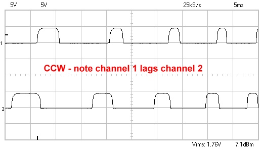
Note that channel 2's pulses are ahead of channel 1's pulses. Here's a trace of the wheel turning clockwise:
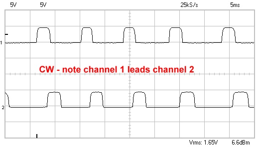
Here, the situation is reversed. Channel 1's pulses arrive before the pulses from channel 2.
Each channel on the PAK-VIIb has an enable input. Suppose you connect the signal from trace 1 to the enable pin and the signal from trace 2 to the corresponding PAK-VIIb input. The enable input only allows the PAK to count edges when it is high. In the first scope picture, then, the PAK will ignore the rising edges on channel 2 because the enable pin will be low. However, it will count the falling edges, since by then the enable signal will be high. Therefore, the falling edge count will tell you how far the wheel traveled in the counter clockwise direction. The duration registers will tell you how fast the wheel is moving if you need to know that.
In the second scope trace, the situation is reversed. The rising edge of pulse 2 occurs during the enable, but the PAK ignores the falling edge. Therefore, the falling edge register tells you the travel distance in the clockwise direction. Of course, which register is which depends on how you hook up the signals. If you put channel 1 on the input and channel 2 on the enable pin, the registers would be reversed (the rising count would indicate counter clockwise).
Circuitry
The exact circuit you'll need will depend on the mouse you use. I gutted a cheap serial mouse. A quick probe with the scope showed me which pins were changing when the wheels spin (you do have to supply the mouse with 5V, of course). The outputs of the phototransistors were not very high level, so I connected each output to the base of a 2N222 through a 1K resistor. The whole circuit looked like this (you have to build two copies; one for each input):
Of course, your mouse may be different. If you are using a commercial shaft encoder, it probably already has 5V outputs.
I connected the PAK to a Basic Stamp 2p just as it shows in the manual:
I connected the Data line to Stamp pin 15 and the Clock line to Stamp pin 14. I also connected a standard RC servo to pin 7 of the Basic Stamp so I could do something interesting with the wheel data. The mouse inputs I connected to P0 (on the diagram above) and pin 18 (this is marked N/C on the schematic, but it is actually the P0 enable).
The RC servo needs power, too, of course. I used 4 AA cells for that (be sure to make a common ground between the digital circuit power supply and the motor supply).
I had in mind to make sort of a software synchro (they tell me no one says selsyn anymore). The idea is that motion in the wheel will cause similar motion on the servo.
Software
Using the PAK-VII library, the main program is pretty simple:
GOSUB freset        ' always reset!
' Turn on pull up resistors for input
fpx=0
GOSUB fpullup

' Read channel 0 all the time
chan=0
clearreg=0
xloop:
  clearchan=0   ' Get the RISE register w/o clearing anything
  register=RISE
  GOSUB FCommand
  i=fpx          ' store answer in temp variable
  register=FALL  ' Now get the FALL register AND clear everything
  clearchan=1
  GOSUB FCommand
  GOSUB style2    ' Now fpx and i have the direction data, so control the servo
GOTO xloop
I used two different servo routines to get different behavior. Here's my first routine that starts the servo spinning in the direction of the wheel turn until you turn the wheel back (this was a modified servo that continuously rotates; you probably shouldn't try this one with a standard servo):
' wheel sets rotation direction speed
style1:
  IF i<>0 OR fpx<>0 THEN  ' if the wheel moved
    IF i>fpx THEN         ' set pulse width
      pw=pw+(i*100)
    ELSE
      pw=pw-(fpx*100)
    ENDIF
    DEBUG DEC i,":",DEC fpx," ",SDEC pw," ", SDEC CENTER+pw,CR
  ENDIF
  PULSOUT SERVO,CENTER+pw   ' spin servo in any case
  PAUSE 20
  RETURN
Changes in the wheel add up to the pulse width in this code.
Here's some code that acts like a synchro (when using a continuously rotating servo):
' Alternate code: servo tracks wheel
style2:
  IF i<>0 OR fpx<>0 THEN
    IF i>fpx THEN
      pw=i*100
    ELSE
      pw=-(fpx*100)
    ENDIF
  DEBUG DEC i,":",DEC fpx," ",SDEC pw," ", SDEC CENTER+pw,CR
  FOR i=1 TO 10
    PULSOUT SERVO,CENTER+pw
    PAUSE 20
  NEXT
  ELSE
    PULSOUT SERVO,CENTER   ' idle
  ENDIF
RETURN
In this case, the servo stays centered unless the wheel moves. When the wheel moves, the code sends 10 pulses in the correct direction to move the servo along with the wheel.
This code is relatively simple. It doesn't track the speed of the wheel. Also, it is possible for the wheel to stop where one of the inputs is always high or even mechanically oscillate. You can detect these conditions by scanning the input pin or examining the duration registers, if it is important.
Of course, mice aren't the only thing that produce quadrature signals. Many shaft encoders (including some built into motors) produce quadrature output. It is easy to make your own encoder wheels (see http://www.portlandrobotics.org/robots/encoders/index.html).
You can visit our PAK-VII page for more information about the device.
Source Code
Here's the entire program including the PAK-VII library:
'{$STAMP BS2p}
'{$PBASIC 2.5}
'{$PORT COM1}
DATAP PIN 15
CLK PIN 14
SERVO PIN 7
CENTER CON 1900   ' center servo position

' Register names
DURLOW CON %000
DURHIGH CON %001
RAWLOW CON %010
RAWHIGH CON %011
RISE CON %100
FALL CON %101
TICK200 CON %110
TICK CON %110
INP CON %110
VER CON %110
SUM CON %111

OUTPUT clk
OUTPUT datap

fpx VAR Word        ' Integer used by some routines
fpb VAR Byte        ' byte
' parameters for FCommand
chan VAR Nib
register VAR Nib
clearreg VAR Bit
clearchan VAR Bit

i VAR Word
pw VAR Word

GOSUB freset        ' always reset!
' Turn on pull up resistors for input
fpx=0
GOSUB fpullup

chan=0
clearreg=0
xloop:
  clearchan=0
  register=RISE
  GOSUB FCommand
  i=fpx
  register=FALL
  clearchan=1
  GOSUB FCommand
  GOSUB style2
GOTO xloop

' wheel sets rotation direction speed
style1:
  IF i<>0 OR fpx<>0 THEN
    IF i>fpx THEN
      pw=pw+(i*100)
    ELSE
      pw=pw-(fpx*100)
    ENDIF
    DEBUG DEC i,":",DEC fpx," ",SDEC pw," ", SDEC CENTER+pw,CR
  ENDIF
  PULSOUT SERVO,CENTER+pw
  PAUSE 20
  RETURN

' Alternate code: servo tracks wheel
style2:
  IF i<>0 OR fpx<>0 THEN
    IF i>fpx THEN
      pw=i*100
    ELSE
      pw=-(fpx*100)
  ENDIF
  DEBUG DEC i,":",DEC fpx," ",SDEC pw," ", SDEC CENTER+pw,CR
  FOR i=1 TO 10
    PULSOUT SERVO,CENTER+pw
    PAUSE 20
  NEXT
  ELSE
    PULSOUT SERVO,CENTER   ' idle
  ENDIF
RETURN

' PAK VII library code from here down

FReset:
LOW DATAP
LOW CLK
HIGH CLK
HIGH DATAP
LOW CLK
RETURN

FCommand:
' inputs chan = channel, register = register, clearreg and clearchan
 fpb=(clearchan<<7) + (clearreg<<6) + (register<<3) + chan
 GOSUB FSendByte
FReadWord:
  SHIFTIN datap,clk,MSBPRE,[fpx.LOWBYTE,fpx.HIGHBYTE]
  RETURN

FTotalReset:
  fpb=$FF
FSendByte:
  SHIFTOUT datap,clk,MSBFIRST,[fpb]
  RETURN

FReadByte:
  SHIFTIN datap,clk,MSBPRE,[fpb]
  RETURN

FPrescale:
' set fpb to the prescale constant
  fpb = fpb + $C0
  GOTO FSendByte

FPullUp:
' set fpx to the pull up mask
  fpb=%11010000
Fscmd:
  GOSUB FSendByte
  fpb=fpx
  GOTO FSendByte

FThresh:
' set fpx to the threshold mask
  fpb=%11010001
  GOTO Fscmd

FSchmitt:
' set fpx to the Schmitt trigger mask
  fpb=%11010010
  GOTO Fscmd
Site contents © 1997-2018 by AWC, Houston TX (281) 334-4341