
AWC Electronics - GP9 Demo
 |
|
Pulse width modulation, or PWM is a trick every embedded developer should have in their toolbox. The idea is simple: Generate a pulse train with a given duty cycle to control the average power sent to some load device. Used with an LED, for example, PWM can dim or brighten the light efficiently and reduce power consumption. Applied to motors, you can control the speed of the motor while maintaining torque. With an RC filter--and maybe an op amp--you can average the pulses into an anlog voltage. Speaking of analog, it is often useful to read analog inputs. In fact, there have been many times I've needed to control a PWM output with an analog input. That's exactly what the GP-9 does.
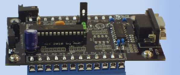
You can read more about the board (pictured above) on the GP-9 page. But the short story is that the board has 5 0-5V analog inputs (8-bit) and 8 PWM outputs. The board starts in one of two modes. In the first mode, the board waits for computer input via an RS232 or USB port. The computer can read the analog inputs, control the PWM outputs, or link the inputs to the outputs.
The second mode doesn't even require a host computer (although you can still use one if you like). In this mode, the board simply outputs 5 PWM outputs based on the 0-5V input on the corresponding analog channel. If channel 1 reads 2.5V, for example, a 50% duty cycle PWM signal will appear on output #1. You can still exercise computer control in this mode, if you like. But for some applications, you don't need a computer at all.
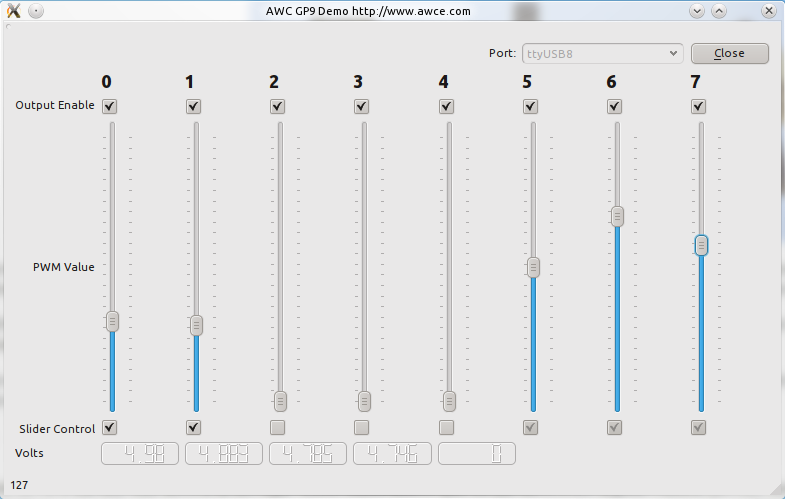
This application note will show you an example program (pictured to the right) that allows you to control the GP9. The program is written using the Qt library and works on Linux or Windows (you could probably port it to the Mac with minimal difficulty). Details about Qt are beyond the scope of this application note, but note that you can download Qt and the tools for it free. The toolkit is licenesed under the LGPL.
The board uses the same low level serial port code that the GP-3 uses. This differs between Linux and Windows (see gp3linux.cpp and gp3win.cpp in the source archive). However, the basic calls do the same job. Namely, open a serial port, read a byte from it, write a byte to it, and close it. The board operates at 9600 baud and uses a similar protocol to the GP3 to ensure the board does not get out of sync with the host computer.
The real heart of things, though, is the GP9 object that represents the board to the rest of the program:
class gp9
{
public:
    gp9(QString _port) { portopen=error=false; port=_port; }  // create with given port (ttyUSB1, COM2, etc.)
     bool open();    // open it up
     bool isOpen();  // determine if open
     bool close();   // close down
     void setpwm(int chan, int pwm);  // set PWM from 0 to 255 on channel 0-7. (Source must be set)
     void setsource(int mask);    // source bits for channel 0-7, 1=slider, 0=analog input
     void setjam(int mask);       // jam channels 0-7 high by setting the corresponding jam bit
     void setoe(int mask);        // output enable for channel 0-7 (0=enabled)
     int readpwm(int chan);       // read back the PWM
     int readad(int chan);        // read analog channel (0-4)
// ought to be protected but since we don't wrap everything they stay public
// so you can manually read/write to the board
     void write(int byte);   // single byte from 00-7F
     void write(int b1,int b2);  // two bytes sent in GP3/GP9 protocol
     int read(void);      // read back a byte
     int getoe(void);     // read back the OE bits
     int getsource(void);  // read back the source bits
     bool error;         // set if error detected

protected:
    QString port;    // port to use
    bool portopen;   // are we open
};
None of these are really Qt-specific except the port name does take a QString.


Reading a value from the board is easy:

int gp9::readad(int chan)
{
    write(0x30+chan);
    return read();
}


The only real trick is when you need to write more than one byte out.  The code to set the PWM, for example, looks simple:


void gp9::setpwm(int chan, int pwm)
{
    write(chan & 7, pwm);
}
The trick is that the two-argument write() call sends the output using the special GP-9 protocol. In this protocol, the most signficant bit of the first byte is always a zero. The same bit in all subsquent bytes (well, in this case the second byte since no commands take more than two bytes total) is a one. Of course, that means you lose a bit in each byte. The protocol specifies that the least significant bit of the second byte is actually the 6th bit of the first byte. That's easier to see by example. Suppose you wanted to write the command "02 01" which would set PWM channel #2 to a value of 1. The actual bytes you would send would be 42 80 (in hex). This way the GP-9 can always synchronize on the first byte. It notices the 6th bit is 1 (40) and strips it off, leaving the actual first command of 02. Then it reads the 2nd byte, strips off the top bit (which must be one) and adds the 6th bit read previously so that the result is, indeed, 02 01.
The GP-9 manual has more details about the protocol and the different commands, most of which are modeled by the gp9 class. Here's the actual write code that implements the protocol:
void gp9::write(int byte)
{
    if (!portopen)
        if (!open()) return;
    gp3write(byte);
}
void gp9::write(int b1, int b2)
{
    if (b2&1) b1|=0x40;  // if 2nd byte ends in 1, set b1.6
    b2>>=1;     // adjust b2
    b2|=0x80;
    write(b1 &0xFF);
    write(b2 &0xFF);
}
The rest is just user interface things, mostly in the main window. The voltmeters update on a timer and the sliders control the PWM outputs as long as the bottom check box is checked. If the box is unchecked, the analog inputs set the outputs. The top checkbox on each channel shuts that channel off if unchecked.
You can download the entire sourcecode (for Linux and Windows).
Site contents © 1997-2018 by AWC, Houston TX (281) 334-4341