AWC Electronics - Relay Coprocessor
On April first, I decided to create a relay-based coprocessor, mostly as an April Fool's joke. What had spurred the idea was two-fold. First, my DDJ Blog was running a series on a selecting relays for specific applications. Second, someone had mentioned to me that to create a two input OR or AND gate with relays, I needed two relays.
That's a common thought--an OR gate is two switches in parallel and an AND gate is two switches in series. That's technically correct, but it isn't optimal. Instead, it is easier to treat a DPST relay as a 2 input multiplexer. A multiplexer can duplicate any logic gate you want.
The video above shows the result. Since a lot of people asked me how it worked,
I decided to provide simple instructions here. The logic controller to the PC
is a
Relay #1 is the SUM relay and Relay #2 is the CARRY relay. In other words,
#1 is an XOR gate and #2 is an AND gate. Note that I cheat a little
and let the PC output B and inverted B (B') so that I don't need a 3rd
relay to implement the XOR gate.
On the GP3 side, I wired A to D0, B to D1, the inverse of B (B') to D2. These are the A and B bit inputs to the adder. The outputs are SUMIN (D7) and CYIN (D6) which give us the sum and carry, respectively.
Here's a run down of the wiring. Since the GP3X has screw terminals and the relays are either in a breadboard (the coils) or screw terminals (the switches) it was simple to wire.
Relay 1: Relay 2:
The relay normally shorts C to NC and when you drive S, it shorts C and NO
(disconnecting NC, of course). Look at Relay 2. If A is 0, C is shorted
to ground which means there is no carry. If A is 1, then C is shorted to B
and that means C=B. This is an AND gate -- any zero causes a zero output.
The only way to get a one is to have A=1 and B=1.
Here's the driving code (or download it):
The delay before reading the relays is important.
The relays need time to operate, plus they are prone to glitches
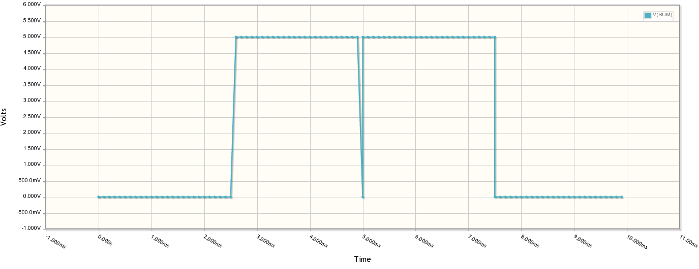
where one bit maybe registered before another one is. For example, look
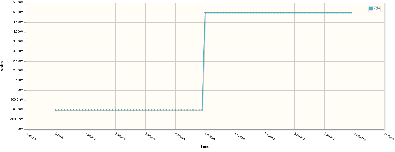
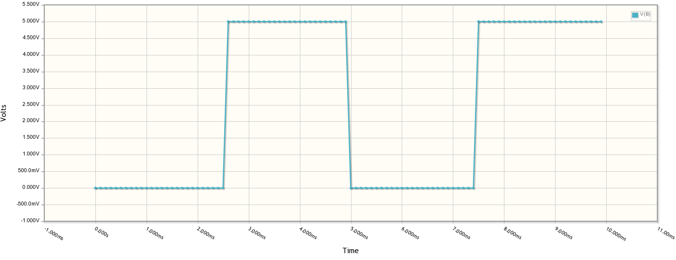
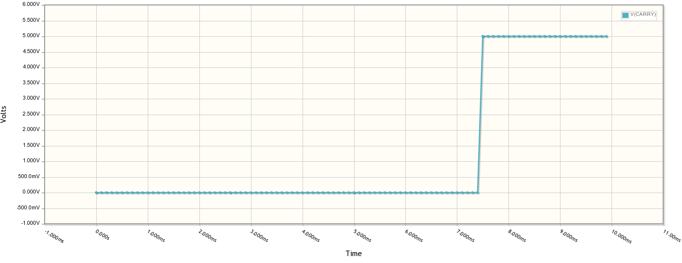
at these plots and notice the glitch on the sum output:
You can do the same simulation, by the way, by clicking the image below.
Useful? Perhaps not. But it is fun to watch your PC compute it old school
with a couple of relays. Plus it sounds like it is working!
+ - 5V
- - Ground
S - D0 (bit A)
NC - D1 (bit B)
NO - D2 (bit B')
C - D7 (SUMIN)
+ - 5V
- - Ground
S - D0 (bit A)
NC - Ground
NO - D1 (bit B)
C - D6 (CYIN)
/* GP3 Relay Calculator
   April 1, 2013 by Al Williams
*/
#include <stdio.h>
#include <string.h>
#include <time.h>
#include <stdlib.h>

#include <gp3lib.h>

// Delay in uS so *1000 if you prefer milliseconds
#define RELAYDELAY (150*1000)

// Set to 1 for extra chatter
#define EXTRACHATTER 1

// GP3 IO Ports
#define AOUT 0
#define BOUT 1
#define BNOTOUT 2
#define SUMIN 7
#define CYIN 6

// Insert a zero to the left of a binary string
void inszero(char *p)
{
  char *pend=p+strlen(p);
  do  // make room, make room
    {
      *(pend+1)=*pend;
      pend--;
    } while (pend!=p);
  *(p+1)=*p;  // save first character
  *p='0';  // replace with '0'
}

// Add two numbers with the
// electromechanical power of relays!
int add2(int a, int b, int *carry)
{
  // Set A and B
  a?gp3high(AOUT):gp3low(AOUT);
  if (b)
    {
      gp3high(BOUT);
      gp3low(BNOTOUT);
    }
  else
    {
      gp3low(BOUT);
      gp3high(BNOTOUT);
    }
  // Let relays do their magic
  usleep(RELAYDELAY);
  // Read carry and sum from relay inputs
  if (carry) *carry=(gp3input(CYIN)=='1');
  return gp3input(SUMIN)=='1';
}

// Zero out A and B
void cleargp3()
{
  gp3low(AOUT);
  gp3low(BOUT);
  gp3high(BNOTOUT);
}

// Set A=B=1 (used for artificial chatter)
void setgp3()
{
  gp3high(AOUT);
  gp3high(BOUT);
  gp3low(BNOTOUT);
}


int readInput(char *s)
{

      scanf("%s",s);
      if (s[0]=='x'||s[0]=='X') return -1;
      if (strspn(s,"01")!=strlen(s))
	{
	  printf("Invalid input!\n");
	  return 0;
	}
      return 1;
}


int main(int argc, char *argv[])
{
  char a[64],b[64];
  char res[65];
  unsigned l;
  int carry0, carry1, lastcarry;
  // Open relay interface
  if (gp3openport(argc<1?argv[1]:"/dev/ttyS1")==-1)
    {
      perror("Error opening relay interface");
      exit(1);
    }
  // set LED on board just to show we are alive!
  gp3setLED(1);
  // A=B=0
  cleargp3();
  // Now get input and do the math
  do
    {
      int n;

      printf("Relay calculator! April 1, 2013 by Al Williams\n");
      printf("Enter two binary numbers A&B\n");
      printf("Enter x to exit\n");
      printf("A: ");
      if (!(n=readInput(a))) continue;
      if (n==-1) break;

      printf("B: ");
      if (!(n=readInput(b))) continue;
      if (n==-1) break;

      memset(res,' ',sizeof(res));
      // Pad both strings with zeros until same size
      while (strlen(a)<strlen(b))
	{
	  inszero(a);
	}
      while (strlen(b)<strlen(a))
	{
	  inszero(b);
	}
      printf("  %s\n+ %s\n",a,b);
      l=strlen(a);
      res[l+1]='\0';
      // start carry chain at 0
      lastcarry=0;
      // While still digitis to go
      while (l--)
	{
	  unsigned idx=l;
	  int temp;
	  int result;
	  // Ask relays for 1/2 add result
	  temp=add2(a[l]=='1',b[l]=='1',&carry0);
	  // Add carry back in for a full add
	  result=add2(temp,lastcarry,&carry1);
	  // Propagate any carry forward
	  lastcarry=carry1||carry0;
	  res[l+1]=result?'1':'0';
	  // Show result (note \r lets us stay on the line)
	  printf(" %s\r",res);
	  fflush(stdout);  // make sure it  writes
// chatter for effect; without this strings of the same bits are boring
#if EXTRACHATTER==1
	  setgp3();
	  usleep(RELAYDELAY);
	  cleargp3();
	  usleep(RELAYDELAY);
#endif
	}
      // show top bit as final carry
      res[0]=lastcarry?'1':'0';
      // Print the whole answer (and new line this time)
      printf(" %s\n",res);
    } while (1);
  // shutdown
  gp3setLED(0);
  cleargp3();
  gp3closeport();
}


Site contents © 1997-2018 by AWC, Houston TX (281) 334-4341